
The path towards decarbonisation of the glass industry with the objective to attain carbon neutrality by 2050 is upon us. It is a trend that we saw coming a few years ago and we have been busy preparing for this transformation. Granted, this is primarily driven by European environmental policies and requirements, at least for now. On the opposite end of the spectrum, the USA – with lower gas costs and fewer incentives or societal pressures – has much less focus on this issue. However, many of our customers at Schneider Electric do have ambitious global corporate sustainability objectives to reduce their CO2 emissions by dates stretching from 2030 to 2050. As a result, we see more and more requirements to significantly increase electrical boosting for facilities all over the world. Indeed, for large glass production companies, their total CO2 emissions are the aggregate emissions of all their plants and facilities globally. With furnace campaigns lasting from a few years up to 10–18 years before the next rebuild/cold repair and with only a few upcoming greenfield projects, the opportunities for these companies to implement carbon-reducing solutions are limited between now and 2050. So, whenever a repair is due now, many glass companies are already considering their options to reduce greenhouse gas (GHG) emissions, particularly by increasing electrical boosting.
The other trend we can see happening in the marketplace is that all types of glass producers are looking into these issues. Going back a few years, we started implementing boosting systems on container glass and pharmaceutical glass furnaces. The size of those furnaces and type of glass made it possible to implement small to medium size electrical boosting (2–5MW). Now, not only is the required size of electrical boosting systems growing from a few MW to over 10MW and beyond, but this trend is happening across most types of glass production, including float glass furnaces. I must say that it is quite striking to see the project sizes of these electrical boosting systems compared to just a few years ago.
A proven technology
Currently, it is recognised that electrical melting and boosting are not the only technologies available to reduce GHG emissions. The other two main energy options being investigated by the industry are hydrogen and biofuel. There is already plenty of research on those and there are some very promising successful tests and industrial implementations on glass furnaces. Nevertheless, in terms on technology readiness, infrastructure, production capacity and ramp-up, hydrogen and biofuels are unlikely to be suitable short term or even midterm solutions for the glass industry’s energy and CO2 challenges. Therefore, I strongly believe that the future systems will be based on a hybrid mix of solutions varying by regions and industries.
The benefit of electrical melting is that it is not only a proven technology, it is already available today for large scale glass furnaces in many regions all over the world. As such, we expect that by 2030–2040, electrical boosting, or shall we say melting, will represent more than 50% of the total melting energy for the majority of new and cold repaired glass furnaces, including for float glass. Indeed, for container glass, the share of electricity will in some cases be much higher, reaching from 80% to a full 100%. Undoubtedly, adoption will be uneven across companies, regions and countries: starting first in Europe followed by Asia Pacific.
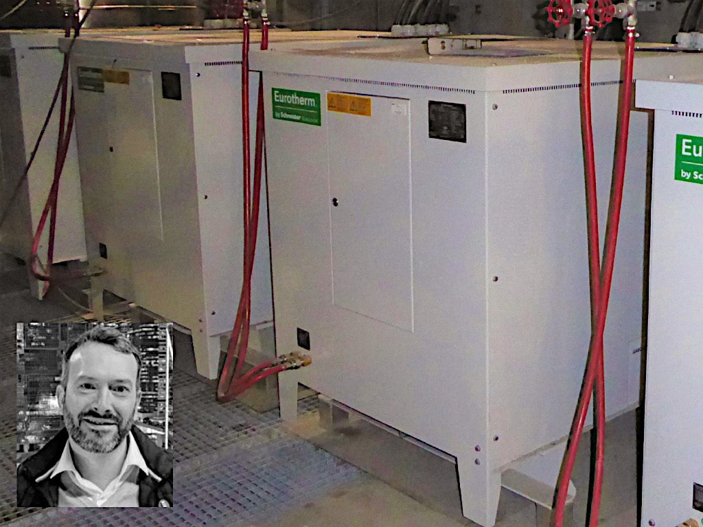
Power boxes
Now if we speak specifically about electrical boosting and melting, there are obviously different ways to implement this. A traditional solution using large variable step-up/step-down transformers has been a very robust technique used for a long time, but we recognised a few years ago that it lacks flexibility. After carefully considering the design, we developed a new Eurotherm power solution in the form of power boxes (power skids), which we have been implementing successfully for over a decade. These power boxes bring new versatility and efficiency with much shorter lead-times and finer granularity of control, as well as easier installation (cables instead of large busbars). With power skids located close to the electrodes (or even underneath the furnace in a few instances, when possible), this solution keeps the voltage as high as possible for as long as possible. The main benefit is that it significantly reduces the line current and the corresponding heat losses. Plus, instead of very expensive copper busbars running over 20–40m or more to the electrodes, it is possible to use much smaller cables.
Energy savings
With a variable transformer design, there is usually a significant difference between the kWs needed to melt the glass and the kVA rating of the transformer, meaning that type of system must be oversized, typically by up to 50% – which increases cost. For example, for a 2MW at 200V system with three single boosting zones, the system would typically be designed at 3MVA (three 1MVA zones). For only 2000kW power needed to melt the glass, such a system instead needs to be designed at typically a minimum of 3000kVA, therefore with three 5000A at 200V busbar systems to the electrodes. That’s a lot of amps and a lot of copper. With the Eurotherm power box solution, an alternative design using a much more standard medium voltage transformer with a secondary voltage between 400 and 480V is possible. Power skids can be placed as close as possible to the electrodes to control and step down the voltage to the desired operating range. Because of the higher voltage and a more efficient system, in this example, the line current from the medium voltage transformer to the three power skids would be less then 2000A, 2.5 times fewer amps than in the traditional design. The high amperage is only after the power skids and therefore on much shorter cable distances to the electrodes. The power skids include power controllers operating in automatic load tap changer mode (digital technology with no mechanical moving parts). As such it provides control of power on the full operating voltage range at very high power factor and without the traditional mechanical wear.
Other concerns to pay attention to when expanding electrical boosting systems are the hazards and costs of traditional oil filled boosting transformers. These can require the installation of expensive sprinkler systems and the construction of reinforced firewalls, plus the associated costly insurance. With the Eurotherm power skids solution, most of the time we can provide a combination of dry and water-cooled options instead, to alleviate those concerns.
Not only do we believe that electrical boosting and melting will play a large role in the decarbonisation of the glass industry, but we also believe that our power skid design methodology — close to the electrodes, is the better way to go.